

I'm hoping a mod can make this a sticky. I have had a number of requests to provide data on the differences between the different 3SGTE pinouts, and I have a hard time just finding the data that I already know exists on the board. So I'm hoping we can consolidate it all in one thread with a proper title, like (I hope) I just made.
Here is the updated and modified info:
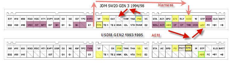
Info on repinning Gen3 as a 94, to run 93+ standalone AEM:
![Image]()
As you can see, the pin labeled "PS" (Further right harness plug, 4th pin from the left on the upper row) is replaced by a pin labeled "ATS" in the later revisions (JDM 1994-1998). Don't know where PS went. Any help?
![Image]()
And here are the "matching pins" for the 91 vs 93 (you need to swap the unhighlighted ones that don't match up to repin a 93 harness to use a 91 EMS, or vice versa)
![Image]()
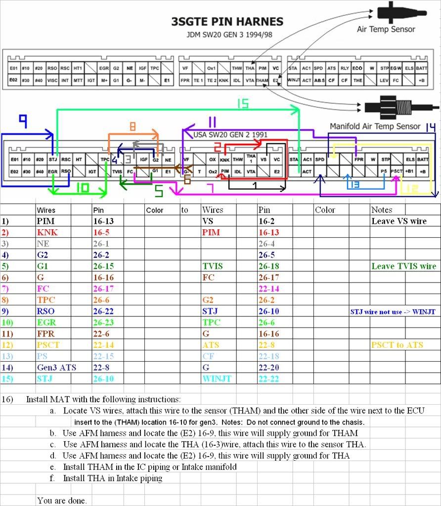
And finally the semi-corrected JDM vs USDM :
![Image]()
Here is a link to the MRControls Website, which details each Pin and it's function:
http://mrcontrols.com/installs/tec3/wiring.htm
Please be sure to point out any inconsistencies so that we may update the diagrams!!
This is a description of each of the pinouts. Originally, it was in order of a Gen3, however as I've updated it its a mix of Gen2/Gen3 and may be out of order depending on which harness you're looking at:
Pin Code Description
A1..BATT.Battery Power - main ECU power
A2..ELS..From Idle Up Diode
A3..EGW..Check Engine Light
A4..STP..From Stop Light
A5..W..Diagnostic Light
A6..ECO..A/C Econ switch?
A7..RLY..TRC?(VTO1)
A8..ATS..From A/C amplifier? (PSCT-> EFI)
A9..SPD..Speed Sensor aka VSS
A10.AC1..From A/C clutch relay
A11.STA..From Starter Relay
A12.B....Power from Circuit Opening Relay - Injector Power
A13.B1...Power from Circuit Opening Relay - Injector Power
A14.FC...Power to Circuit Opening Relay - Fuel Pump Power
A15.LEV..TRC?(VTO2)
A16.CCO..?
A17..THE..Temp?
A18..ABV..Idle Up?(PS->IDUP)
A19..CF..?
A20..ABS..ABS
A21..ACT..From A/C amplifier
A22..WINJ..TRC?(TR1)
B1..TVIS - factory TVIS SWITCH
B2..TPC..(Turbo) TVSV (factory boost controller - ecu pulses GRD here)
B3..IGF..Ignitor. Description: is produced by the igniter when it successfully fires the coil. The ECU looks at this signal as an affirmation that the ignition is working properly and it can continue to operate. If the IGF signal is not detected for several consecutive engine cycles, the ECU sets code 14 and stops the engine.
B4..NE..Ref/Sync crank sensor
B5..G2..Ref/Sync cam sensor
B6..EGR..EGR VSV
B7..EVP1..Evaporative VSV
B8..HT1..Oxygen Sensor Heater
B9..RSC..Idle Speed Control
B10..RSO..Idle Speed Control
B11..#20..#2 Injector
B12..#10..#1 Injector
B13..EOI..Ground
B14..E1..Ground
B15..-..
B16..M-..TRC (Japan only traction control, secondary idle swtch)
B17..G-..Ref/Sync (cam or crank?)
B18..G1..Ref/Sync (cam or crank?)
B19..M+..TRC?(IDL2) Secondary TP Sensor
B20..IGT..Ignitor. Description: IGT is produced by the ECU. It is a 5V signal indicating that the igniter should fire the coil.
B21..MTT..TRC?(NEO)
B22..INT..Fan?(FAN)
B23..VISC..
B24..#40..#4 Injector
B25..#30..#3 Injector
B26..EO2..Ground
C1..VC.. +5v reference (for MAP Sensor etc)
C2..PIM..MAP Sensor analog input
C3..THA..Intake airbox temp
C4..THW..Engine Water Temp
C5..VS...AFM analog output
C6..OX1..Oxygen Sensor
C7..VTA2..Throttle Pos Sensor #2 (for TRC)
C8..VF..Check Connector
C9..E2..Ground
C10..THG (THAM later models)..Intake Manifold Temp Sensor
C11..VTA..Throttle Pos Sensor
C12..IDL..Cruise Control/Throttle Pos
C13..KNK..Knock Sensor
C14..TE2..Check Connector
C15..TE1..Check Connector
C16..FPR..Fuel Pump Relay
11/19/06: Great info on rewiring a 5S harness to control a 3SGE (non turbo!) motor
4/26/07: Thread I started on EA1 - white plug that connects the body harness DIRECTLY to the motor harness.
3/10/08:Finally some Caldina info getting out
![Image]()
Here is the updated and modified info:
Info on repinning Gen3 as a 94, to run 93+ standalone AEM:
As you can see, the pin labeled "PS" (Further right harness plug, 4th pin from the left on the upper row) is replaced by a pin labeled "ATS" in the later revisions (JDM 1994-1998). Don't know where PS went. Any help?

And here are the "matching pins" for the 91 vs 93 (you need to swap the unhighlighted ones that don't match up to repin a 93 harness to use a 91 EMS, or vice versa)

And finally the semi-corrected JDM vs USDM :

Here is a link to the MRControls Website, which details each Pin and it's function:
http://mrcontrols.com/installs/tec3/wiring.htm
Please be sure to point out any inconsistencies so that we may update the diagrams!!
This is a description of each of the pinouts. Originally, it was in order of a Gen3, however as I've updated it its a mix of Gen2/Gen3 and may be out of order depending on which harness you're looking at:
Pin Code Description
A1..BATT.Battery Power - main ECU power
A2..ELS..From Idle Up Diode
A3..EGW..Check Engine Light
A4..STP..From Stop Light
A5..W..Diagnostic Light
A6..ECO..A/C Econ switch?
A7..RLY..TRC?(VTO1)
A8..ATS..From A/C amplifier? (PSCT-> EFI)
A9..SPD..Speed Sensor aka VSS
A10.AC1..From A/C clutch relay
A11.STA..From Starter Relay
A12.B....Power from Circuit Opening Relay - Injector Power
A13.B1...Power from Circuit Opening Relay - Injector Power
A14.FC...Power to Circuit Opening Relay - Fuel Pump Power
A15.LEV..TRC?(VTO2)
A16.CCO..?
A17..THE..Temp?
A18..ABV..Idle Up?(PS->IDUP)
A19..CF..?
A20..ABS..ABS
A21..ACT..From A/C amplifier
A22..WINJ..TRC?(TR1)
B1..TVIS - factory TVIS SWITCH
B2..TPC..(Turbo) TVSV (factory boost controller - ecu pulses GRD here)
B3..IGF..Ignitor. Description: is produced by the igniter when it successfully fires the coil. The ECU looks at this signal as an affirmation that the ignition is working properly and it can continue to operate. If the IGF signal is not detected for several consecutive engine cycles, the ECU sets code 14 and stops the engine.
B4..NE..Ref/Sync crank sensor
B5..G2..Ref/Sync cam sensor
B6..EGR..EGR VSV
B7..EVP1..Evaporative VSV
B8..HT1..Oxygen Sensor Heater
B9..RSC..Idle Speed Control
B10..RSO..Idle Speed Control
B11..#20..#2 Injector
B12..#10..#1 Injector
B13..EOI..Ground
B14..E1..Ground
B15..-..
B16..M-..TRC (Japan only traction control, secondary idle swtch)
B17..G-..Ref/Sync (cam or crank?)
B18..G1..Ref/Sync (cam or crank?)
B19..M+..TRC?(IDL2) Secondary TP Sensor
B20..IGT..Ignitor. Description: IGT is produced by the ECU. It is a 5V signal indicating that the igniter should fire the coil.
B21..MTT..TRC?(NEO)
B22..INT..Fan?(FAN)
B23..VISC..
B24..#40..#4 Injector
B25..#30..#3 Injector
B26..EO2..Ground
C1..VC.. +5v reference (for MAP Sensor etc)
C2..PIM..MAP Sensor analog input
C3..THA..Intake airbox temp
C4..THW..Engine Water Temp
C5..VS...AFM analog output
C6..OX1..Oxygen Sensor
C7..VTA2..Throttle Pos Sensor #2 (for TRC)
C8..VF..Check Connector
C9..E2..Ground
C10..THG (THAM later models)..Intake Manifold Temp Sensor
C11..VTA..Throttle Pos Sensor
C12..IDL..Cruise Control/Throttle Pos
C13..KNK..Knock Sensor
C14..TE2..Check Connector
C15..TE1..Check Connector
C16..FPR..Fuel Pump Relay
11/19/06: Great info on rewiring a 5S harness to control a 3SGE (non turbo!) motor
4/26/07: Thread I started on EA1 - white plug that connects the body harness DIRECTLY to the motor harness.
3/10/08:Finally some Caldina info getting out


") Do NOT even attempt this. Get a harness as ricky mentioned!!
Do NOT even attempt this. Get a harness as ricky mentioned!!

