
some of you guys enjoy the progress along the way, so this isn't ready for sale yet but this thread is for the kit development.
This kit will only be for the belt routing to allow the stock TRD/Lotus supercharger to be used. a kit will follow later with an intake manifold that can use cheaper superchargers as well as larger superchargers and likely also support intercooling.
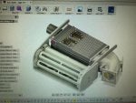
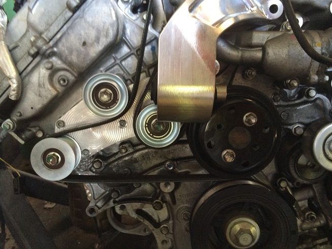
so without delay, the first lower pulley prototype came in today:
![Image]()
I'm pretty happy with it, right now it is using the HKS pulleys and they aren't available off the shelf so i'll have to make some of a similar size.
For the upper idler i'll use the same design i previously used. so i need to get it all installed on a car and get a properly sized belt.
This kit will only be for the belt routing to allow the stock TRD/Lotus supercharger to be used. a kit will follow later with an intake manifold that can use cheaper superchargers as well as larger superchargers and likely also support intercooling.
so without delay, the first lower pulley prototype came in today:
I'm pretty happy with it, right now it is using the HKS pulleys and they aren't available off the shelf so i'll have to make some of a similar size.
For the upper idler i'll use the same design i previously used. so i need to get it all installed on a car and get a properly sized belt.
")